Q: I need an expert opinion on valve position feedback for ball valves with Rexa or EIM actuators. I want to know if there are any other ways to know the true position besides those based on the actuator.
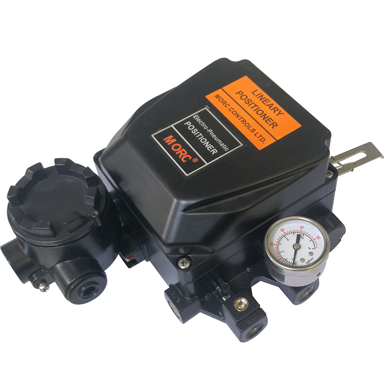
Hiten A. Broker, PE PMP Butterfly Valve With Positioner

If the valve has no positioner, one can also install an encoder directly on the valve stem. There are two main types of rotary encoders: absolute and incremental. The output of an absolute encoder indicates the current shaft position, making it an angle transducer. Rotary encoders are used on industrial controls and robotics as computer input devices.
The magnetic encoders have two or more magnetic poles, and their pole positions are typically read by magneto-resistive or Hall Effect sensors. This code can be read by a microprocessor or microcontroller to determine the angle of the shaft, like an optical encoder. These encoders are best used in conditions where other types of encoders may fail due to accumulated dust or debris. Magnetic encoders are also relatively insensitive to vibrations, minor misalignment or shocks.
A2: The two ways you can accurately measure the position of a ball valve are:
1. Use the position of the actuator to define the position of the valve.
2. Install a rotary encoder on the shaft of the valve that measures the actual shaft movement.
The second method, besides being difficult to implement, has accuracy issues because the movement required in stroking a 90° rotary valve is low. On a ball valve smaller than 2 inches, the actual movement measured would be around 1.5 inches, where it may be closer to 4 inches or more for a linear actuator.
Q: In your book, Instrument Engineers’ Handbook, your examples are mostly about fluids and not dust-laden gases (such as flue gases). My need is for sealed sensors. I’d like to learn who manufactures these, so I could approach them. We have challenges from dust particles affecting total air measurement on our forced-draft (FD) fans. The dust comes from recirculation lines that feed back to the FD fan suction used during boiler start up, which we use for dew point control
Richard Mahupete Komati Power Station
A1: To clarify this question for the reader, I show in Figure 2 a complete boiler control system, modified (in red). It shows the recirculation of the combustion product, which from the discharge of the induced draft (ID) fan, is recirculated back to the suction of the FD fan for humidity control. The question asks for advice on selecting the total-combustion airflow detector (FT-104, in red).
For such applications areas, pitot traverse stations (Figure 3) are most often used. They’re supplied by Fluke, Air Monitor, etc, to detect the average air flow velocity, which is then converted into volumetric flow. On dusty applications, such as when the boiler fuel is coal and the combustion air includes dusty flue gas, these pitot transfer stations require air purging. If periodically heavy purging is required, it can be initiated manually. But while it occurs, the flow control loop should be switched to manual.
The area of the transfer station (rectangular or circular as shown on the left of Figure 3) is segmented into equal area sections, each with a pitot sensor in its center. Each sensor detects both the total impact pressure (Pi) and the static pressure (Ps) at that point, and then into the two manifolds that act as averaging chambers (see right of Figure 3). The difference between these two averaged values (ΔP = ΣPi - ΣPs) is measured by a d/p sensor, which converts it into volumetric flow.
Because these pitot stations generate very small pressure differentials, special d/p cells are required to detect minute signals. One such detector is the membrane-type design. Flow nozzles can be placed in front of the area-averaging transfer station to increase the ΔP they generate and reduce their straight pipe run requirement. On dusty applications, which require purging, the purge flow rate during measurement must be kept constant. Also, the pressure drop between the station and the d/p cell must be minimized with short, large-diameter connecting tubes.
If the dust isn’t sticky and the air temperature is constant and doesn’t exceed the manufacturer's limits, thermal flow probes can also be considered for this measurement. But based on your description of the application, I wouldn’t recommend them.
A2: Many of the standard manufacturers, such as Rosemount, Endress+Hauser, ABB and Honeywell, build transmitters that have sealed sensors.
But, to be able to give a better answer, you need to supply more detailed information, such as use of the instrument, process variables, type of dust contaminants and concentrations, etc., since some may have easy solutions while other applications may be more complex.

Electropneumatic Valve A3: You might try using a thermal mass flow sensor that inserts into your stack connected to a transmitter.